


LED Headlight Bulb Beam Pattern Adjustment Guide

Table of Contents
- Understanding LED Headlight Beam Patterns and Cutoff Lines
- LED Headlight Bulb Alignment: Why Bulb Orientation Determines Everything
- Headlight Adjustment Tools You Actually Need
- Step-by-Step: How to Adjust LED Headlight Beam Pattern
- Troubleshooting Dark Spots, Glare, and Scattered Light
- DOT Headlight Compliance Standards and Legal Fitment
- Conclusion
- Frequently Asked Questions
Last Updated: September 28, 2026
Understanding LED Headlight Beam Patterns and Cutoff Lines
A headlight beam pattern is the shape of light a bulb throws onto the road; the cutoff line is the sharp upper edge that keeps that light out of oncoming drivers' eyes. Get it wrong and you either blind other drivers or light up nothing but treetops. This LED headlight bulb beam pattern adjustment guide from RMS Lighting LLC walks through the process, from reading a beam pattern to fine-tuning it with basic hand tools.
Projector vs. Reflector Housing: How Each Shapes the Beam
Projector housings use a lens and a shield to cut a crisp, focused beam. Reflector housings bounce light off a mirrored bowl, so the pattern depends on where the bulb's light source sits.
- Projector lens: sharp cutoff, tight hotspot, less stray light
- Reflector housing: wider spread, softer cutoff, more sensitive to bulb position
- Both: depend on the LED chips sitting exactly where the factory filament sat
LED Headlight Bulb Alignment: Why Bulb Orientation Determines Everything
LED headlight bulb alignment comes down to one rule: the LED chips must face left and right, never up and down. Halogen filaments emit light in all directions from a single point. LED bulbs use chips mounted on two sides, so their light only emits sideways.
Headlight Adjustment Tools You Actually Need
You need fewer tools than most guides suggest. A Phillips screwdriver, a tape measure, and a wall are enough for 90% of vehicles.
- Tape measure for marking height on the wall
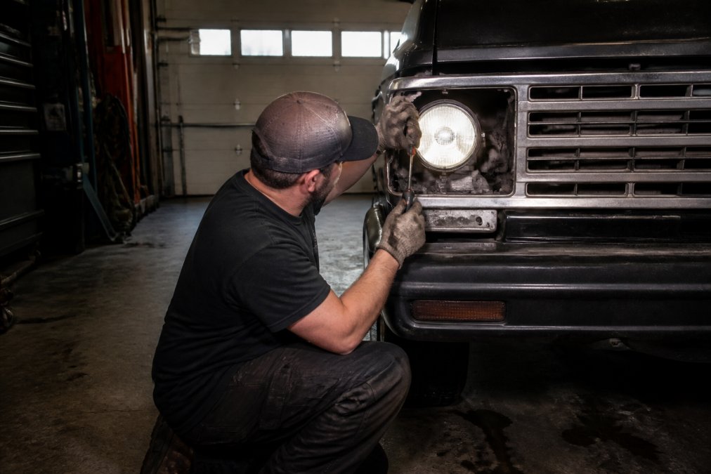
- Phillips and flathead screwdrivers for adjustment screws
- Painter's tape to mark your reference lines
- A level floor and a wall at least 25 feet away
- Your owner's manual to locate the vertical and horizontal adjusters
Step-by-Step: How to Adjust LED Headlight Beam Pattern
Beam pattern adjustment is a repeatable process: park square to a wall, mark your reference height, then tune the vertical and horizontal adjusters until the cutoff sits just below the mark. The job takes about 30 minutes on most vehicles.
The Standardized Wall Test: Distance, Height, and Reference Lines
Most guides tell you to "park 25 feet from a wall" and stop there. That number comes from the federal aiming geometry used in inspection shops, and it matters because the cutoff drop is measured as an angle, not a fixed number of inches. At 25 feet, a 0.5-degree downward angle drops the cutoff roughly 2.6 inches below the lamp centerline; at 10 feet, the same angle drops it about 1 inch.
Here is the calibration setup that actually works:
- Find a level surface. A sloped garage floor skews the whole test; roll the vehicle a few feet and re-check if your phone's bubble level shows tilt.
- Set tire pressure and fuel level first. Ride height changes aim, and a half-tank difference can move the cutoff noticeably on soft-sprung vehicles.
- Park 25 feet from a flat, light-colored wall, perpendicular to it. Measure from the wall to the center of each headlight lens, not the bumper.
- Mark the lamp centerline. Measure from the ground to the center of each headlight and run painter's tape horizontally across the wall at that height. Label left and right.
- Mark the vertical centerline. Have a helper sight down the center of the vehicle, or drop a plumb line from a center reference point, and tape a vertical line on the wall.
- Turn on low beams only. High beams and fog lights confuse the pattern read.
- Read the cutoff. A projector shows a sharp horizontal line with a step or "shelf" on the driver's side; a reflector's line is softer and may fade rather than cut.
- Adjust vertical first. Turn the vertical adjuster until the flat portion of the cutoff sits 2 to 4 inches below the tape line, with the step (if present) at or just below it.
- Adjust horizontal second. The hotspot or vertical step should land on or just inside the vertical centerline for each lamp; on most vehicles the driver-side beam aims slightly lower and more inboard to protect oncoming traffic.
- Cover one lamp at a time. A folded towel over the lens isolates each pattern so you are not chasing two beams at once.
- Recheck together. Both cutoffs should sit at the same height and overlap without crossing; crossing beams mean the horizontal aim is off.
Reading the Cutoff Step
The asymmetric step in a low beam is not a defect, it lets you see the shoulder and signs on the passenger side while keeping light out of oncoming windshields. On a projector it is a hard vertical jog; on a reflector, a gentle rise. If your step is on the wrong side, your bulb is rotated 180 degrees in the collar.
Distance Cheat Sheet
If you cannot get 25 feet of clear space, scale the target drop at shorter distances:
- 25 feet: 2 to 4 inches below lamp centerline (standard)
- 15 feet: roughly 1.5 to 2.5 inches below
- 10 feet: roughly 1 to 1.5 inches below
Visual Calibration: The Wall Test Method
The wall test method replaces a four-figure aiming machine with tape and a flat wall. Look for four things: a sharp cutoff line, a centered hotspot, a step on the correct side, and no light spilling above the line.
Troubleshooting Dark Spots, Glare, and Scattered Light
Most beam pattern problems trace back to one of three root causes: the LED chips are not sitting where the factory filament sat, the bulb is rotated off-axis, or the housing's optical design does not match the bulb's emission pattern. The fix depends on which housing you have, because projectors and reflectors fail in different ways.
Projector vs. Reflector: Different Failures, Different Fixes
Projector housings use a lens and a cutoff shield. The shield creates the sharp line, and the lens focuses the light. When a projector beam goes wrong, it usually fails in one of these ways:
-
Dark spot in the center of the hotspot: the LED chip is too far forward or too far back from the shield. Projectors are unforgiving about focal distance. A bulb that is 1 to 2 mm off from the factory filament position will throw a shadow.
-
Glare above a sharp cutoff: the bulb is rotated so the chips face up and down instead of left and right. The shield cannot block light that is emitted above its edge.
-
Double cutoff line: the two LED chips are not aligned with each other, or the bulb is tilted in the collar. This is common on cheaper bulbs with loose tolerances.
-
Scattered light with no clear cutoff: the bulb emits light in a pattern the reflector was not designed for. Reflectors are shaped around a point source, and a two-sided LED chip is not a point source.
-
Dark spots off to the sides: the chips are rotated off-axis, so the reflector is throwing light into the wrong part of the bowl.
-
Hotspot too high or too low: the bulb is seated at the wrong depth. Reflectors have a sweet spot, and moving the bulb even a few millimeters shifts the hotspot.
Work Through the Fixes in Order
- Confirm orientation first. Chips face left and right, never up and down. This is the single most common cause of glare and dark spots.
- Check seating depth. Compare the LED bulb's chip position to the factory halogen filament position. If the chips sit deeper or shallower, the beam will be off.
- Rotate the collar. If your bulb has a rotatable collar, spin it 90 degrees and recheck. Some housings want the chips at a slight angle rather than perfectly horizontal.
- Swap bulbs left to right. If the problem follows the bulb, it is a bulb fault. If it stays with the housing, it is an aim or housing issue.
- Re-aim the housing. After any bulb change, redo the wall test. Do not assume the previous aim still holds.
Heat Dissipation and Beam Stability
An LED bulb's output and color temperature depend on how well it sheds heat.
What to watch for:
- Color shift toward yellow or orange after extended use usually means the chips are running hot.
- Cutoff softening as the bulb heats can push light above the line that was previously blocked.
- Flickering or dimming at idle can indicate a driver or ballast issue, not a bulb issue.
| Problem | Likely Cause | Fix |
|---|---|---|
| Dark spots in pattern | Chips rotated off-axis or wrong seating depth | Rotate collar 90 degrees; verify depth against factory bulb |
| Glare above cutoff | Bulb seated wrong depth or chips facing up/down | Reseat, lock the ring, confirm chip orientation |
| Scattered light | Bulb not matched to housing optics | Verify fitment and orientation; consider a different bulb design |
| Double cutoff line | Chips misaligned or bulb tilted in collar | Reseat bulb; check collar lock |
| Beam drifts over time | Heat-related output shift | Check cooling fan operation; consider an actively cooled bulb |
DOT Headlight Compliance Standards and Legal Fitment
DOT headlight compliance standards govern what you can legally run on public roads, and they are enforced at the state level through inspection programs. Federal rules require headlamps to meet FMVSS No. 108, the federal standard for vehicle lighting, which sets limits on beam pattern, glare, and mounting height.
| Problem | Likely Cause | Fix |
|---|---|---|
| Dark spots in pattern | Chips rotated off-axis | Rotate collar 90 degrees |
| Glare above cutoff | Bulb seated wrong depth | Reseat and lock the ring |
| Scattered light | Bulb not matched to housing | Verify fitment and orientation |
| Beam drifts over time | Heat-related output shift | Check cooling fan operation |
Conclusion
Getting a clean cutoff line and a centered hotspot takes patience, but the payoff is real: better road visibility and no angry flashes from oncoming drivers. The bulbs you start with set the ceiling on how good that pattern can get.
Frequently Asked Questions
How should LED headlight bulbs be positioned in the housing?
LED bulbs must be positioned so the diode chips face left and right (3 and 9 o'clock) when seated in the housing. This orientation replicates the filament placement of the original halogen bulb and produces the correct beam pattern. Many LED bulbs include a rotatable collar that lets you spin the bulb body independently of the locking ring. Loosen the collar, rotate the bulb until the chips sit horizontally, then tighten the collar against the housing. Incorrect orientation causes scattered light, dark spots, and glare for oncoming drivers.
Do I need to adjust my headlights after installing LED bulbs?
Yes. Even if the bulb is seated correctly, the beam pattern adjustment may shift because LED chips sit at a slightly different depth than a halogen filament. After installation, park 25 feet from a flat wall on level ground and check where the cutoff line falls. The top of the low beam cutoff should sit about 2 inches below the horizontal centerline of the headlight. If it is higher or lower, use the vertical adjustment screw on the housing to correct it. Skipping this step is the most common reason LED upgrades blind other drivers.
What is a headlight cutoff line and why does it matter?
The cutoff line is the sharp upper edge of your low beam pattern where light stops and darkness begins. It protects oncoming drivers from glare while keeping the road ahead illuminated. A proper cutoff line is flat on the driver's side and steps up slightly on the passenger side to light road signs. If the cutoff is blurry, too high, or nonexistent, your LED bulbs are either misaligned or incompatible with the housing. A clean cutoff line is the single best indicator that your beam pattern adjustment is correct.
What tools do I need for headlight adjustment?
You need a Phillips or flathead screwdriver (size varies by vehicle), a Torx bit set for some domestic and European models, a 10mm wrench for certain adjustment nuts, and a tape measure. A piece of painter's tape helps mark reference lines on the wall. Park on level ground 25 feet from a flat wall, and have about 15 feet of clear space behind the vehicle. No specialty headlight adjustment tools are required for most cars, though some housings use recessed screws that need a long-shaft screwdriver or a ratcheting bit driver.