



Install Anti-Flicker Resistors for Truck LEDs

Table of Contents
- What Is Hyperflashing and Why Anti-Flicker Resistors Matter
- How Load Resistors Work to Fix LED Hyperflash
- Tools and Materials You'll Need
- Understanding Load Resistor Wiring Diagrams
- Step-by-Step Installation Guide for Anti-Flicker Resistors
- Best Practices for LED Resistor Mounting and Heat Management
- Common Mistakes to Avoid
- Frequently Asked Questions
Last Updated: September 26, 2026
What Is Hyperflashing and Why Anti-Flicker Resistors Matter
Hyperflashing occurs when LED turn signals blink at double or triple speed because LEDs draw far less current than factory halogen bulbs, a problem that anti-flicker resistors LED solutions address. Your truck's flasher relay, designed for the old bulbs, detects the lower current and thinks a bulb burned out, so it pulses faster trying to get a response.
Anti-flicker resistors solve this by mimicking the electrical draw of a factory bulb, tricking your flasher into working normally while absorbing extra power as heat.
Hyperflashing looks unprofessional and signals a problem to other drivers. Installing anti-flicker resistors solves this instantly, delivering smooth factory-style blinking without warning lights or error codes.
The fix is simple, affordable, and takes about an hour for DIY truck owners comfortable with basic wiring.
How Load Resistors Work to Fix LED Hyperflash
A load resistor creates resistance that converts electrical energy into heat. Installed in parallel with your LED turn signal, it draws current alongside the LED.
Your flasher relay sees the combined current, thinks it's a normal halogen bulb, and cycles at the correct speed.
Your factory flasher relay needs minimum current to operate correctly. Halogen bulbs draw 5-10 amps; LEDs draw less than 1 amp. The resistor fills that gap.
The resistor doesn't affect LED brightness since it sits in parallel, allowing electricity to flow through both simultaneously. Nearly all current goes through the LED path (which has almost no resistance), while the resistor pulls enough extra current to satisfy your truck's electrical system.
A 50-watt resistor works for most applications. Some newer trucks with advanced electronics need a CANbus module instead, which tricks the computer rather than the flasher relay.
Tools and Materials You'll Need
Tools:
- Wire stripper (12-18 gauge capacity)
- Soldering iron (25-40 watts) or crimp connectors
- Heat gun or lighter for heat shrink tubing
- Multimeter (to test continuity)
- Screwdrivers (Phillips and flathead)
- Pliers or needle-nose pliers
- Test light or continuity tester
Materials:
- Load resistor (50-watt minimum, correct ohm rating for your truck)
- Heat shrink tubing (assorted sizes)
- Electrical tape
- Quick splice connectors (optional, but recommended)
- Solder and flux (if soldering instead of crimping)
- Wire (12-gauge, if you need to extend connections)
Use a clean work surface and good lighting. A trouble light helps you see inside the turn signal housing.
Understanding Load Resistor Wiring Diagrams
A load resistor wiring diagram shows where the resistor connects in your circuit using standard symbols: circles for connections, lines for wires, and rectangles for components.
Your turn signal circuit has three main parts: power source (battery), control (flasher relay), and output (turn signal light). The resistor installs in parallel with the turn signal bulb, so both connect to the same two wires.
The hot wire carries power from the flasher; the ground wire completes the circuit back to the battery. Your resistor's two leads connect one to each wire.
Newer models may have a body control module (BCM) managing lighting. Find your truck's wiring diagram in the owner's manual or online by searching your truck's year, make, and model plus "wiring diagram turn signal."
The diagram tells you which color wires to use. Factory colors are standardized: yellow or amber for turn signals, black for ground. Using the wrong wires means your resistor won't work or you'll damage something else.
Step-by-Step Installation Guide for Anti-Flicker Resistors
Step 1: Locate and Disconnect the Factory Turn Signal
Park your truck and turn off the engine. Remove the negative battery terminal to cut all power. Wait five minutes for capacitors to discharge.
Locate your turn signal assembly, typically in the front fender or bumper. You may need to remove the lens cover or trim panels. Check your owner's manual for the exact process.
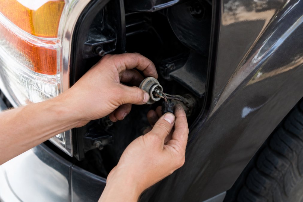
Twist the turn signal bulb socket counterclockwise and pull it straight out. Keep track of driver and passenger side, as they're separate circuits.
Disconnect the old LED bulb or factory halogen bulb. You'll replace it with your new LED after the resistor is installed.
Step 2: Identify the Hot Wire and Ground Wire
Locate the wiring harness connecting to your turn signal. Use your wiring diagram to identify which wire is hot and which is ground.
The hot wire carries power; the ground wire completes the circuit. Ignore any third wire for running lights.
Set your multimeter to voltage mode. Have someone turn on the turn signal while you probe each wire. The hot wire shows 12 volts; the ground wire shows zero. Mark these wires with tape.
Never guess. A wrong connection shorts your circuit or blows a fuse.
Step 3: Splice the Resistor Into the Circuit
You can solder (stronger connection) or crimp (faster, less skill required).
For crimping: strip half an inch of insulation from both the hot wire and resistor lead. Insert both into a quick splice connector and squeeze with pliers until you hear a click.
For soldering: strip half an inch from both wires, twist together, heat for 3-5 seconds, apply solder to coat the connection, and let cool for 30 seconds.
After joining the wires, cover the connection with heat shrink tubing. Slide the tubing over the joint. Use a heat gun or lighter to shrink it tight. This prevents moisture from corroding the connection.
Repeat this process for the ground wire and the other resistor lead.
Step 4: Mount and Secure the Resistor
This is critical. A resistor that moves around will eventually break and cause problems. Heat also demands proper mounting.
Resistors get hot during operation, hot enough to melt plastic. Never mount a resistor directly against plastic trim or wiring. Use a metal surface instead. Your truck's frame, chassis, or a metal bracket works perfectly.
Use thermal adhesive or a small metal bracket to secure the resistor to a metal surface. Make sure air can flow around it. Don't bury it in a tight space where heat builds up.
Some installers use zip ties to secure the resistor to the wiring harness. This works if you position it away from plastic components. The resistor should have at least an inch of clearance from anything flammable.
Test the resistor by touching it after running your turn signal for 30 seconds.
Step 5: Test the LED Turn Signal
Before you celebrate, verify everything works.
Reconnect your negative battery terminal. Turn on your truck. Activate the turn signal on the side where you installed the resistor. It should blink at normal speed, about once per second. No hyperflashing. No dimming. No warning lights on your dashboard.
Best Practices for LED Resistor Mounting and Heat Management
Heat kills electronic components. Managing it properly extends the life of your resistor and keeps your truck safe.
Common Mistakes to Avoid
Most problems come from rushing or skipping steps.
Using undersized resistors is the biggest mistake. A 25-watt resistor overheats and fails. Use 50 watts minimum. Check your truck's specific requirements before ordering.
| Mistake | Problem | Fix |
|---|---|---|
| Undersized resistor | Overheating, burnout | Use 50W minimum |
| Plastic mounting | Melting, fire risk | Mount to bare metal |
| Wrong wire identification | Shorts, component damage | Use multimeter to verify |
| No heat shrink | Corrosion, intermittent failure | Cover all connections |
| LED installed first | Can't diagnose resistor issues | Test resistor with factory bulb |
| Ignoring dashboard warnings | BCM rejects the setup | Install CANbus module instead |
Frequently Asked Questions
How do I install load resistors for LED blinkers?
Install load resistors by splicing them into the turn signal circuit between the hot wire and the LED. Strip about 1/2 inch of insulation from both the signal wire and resistor wire, then use a wire tap connector or solder the connection. Secure the resistor to a metal heat sink using thermal adhesive or a mounting bracket. Finally, test the turn signal to confirm the hyperflashing has stopped and the LED blinks at the correct rate.
What wattage resistor do I need for my LED turn signals?
The resistor wattage depends on your LED's power draw and the original bulb's resistance. Most truck LED turn signal conversions require a 50-watt resistor. Consult the LED kit documentation or use a multimeter to measure the current draw of your LED, then calculate the required wattage using Ohm's law.
Where should I mount the load resistor to avoid overheating?
Mount the resistor to a metal surface (chassis ground or heat sink) to dissipate heat safely. Avoid mounting near plastic components, wiring harnesses, or fuel lines. Use thermal adhesive or a mounting bracket rated for automotive use. Ensure there is airflow around the resistor. Check the resistor temperature after 10 minutes of operation; it should be warm but not too hot to touch. Proper mounting prevents thermal damage and extends the resistor's lifespan.
Why do my LED turn signals still hyperflash after installing a resistor?
Hyperflashing may persist if the resistor wattage is incorrect, the connection is loose, or the resistor is not properly grounded to the chassis. Verify the resistor is rated for your LED's power draw and that all wire splices are secure. Test with a multimeter to confirm voltage drop across the resistor. Some modern trucks use a CAN-bus system that may require a dedicated LED-compatible flasher relay instead of a resistor. Consult your vehicle's wiring diagram.