



LED Turn Signal Wiring Issues: Troubleshooting Guide

Table of Contents
- Diagnose Your LED Turn Signal Problem: A Symptom-Based Flowchart
- Why LED Turn Signal Bulbs Not Flashing: Common Causes
- Fixing LED Turn Signal Hyperflash: Relay and Load Solutions
- LED Turn Signal Resistor Installation: Step-by-Step
- LED Turn Signal Bad Ground Symptoms: Testing and Repair
- Inspecting Bulb Sockets, Wiring Harness, and Electrical Connections
- Testing LED Turn Signal Circuits: Multimeter Basics
- When to Replace, Repair, or Seek Professional Help
- Frequently Asked Questions
Last Updated: October 8, 2026
Diagnose Your LED Turn Signal Problem: A Symptom-Based Flowchart
Swapping incandescent turn signal bulbs for LEDs causes predictable problems, and most LED turn signal wiring issues follow a clear diagnostic path. Identify the symptom before tearing into your electrical system.
Start simple: no light means a load or circuit issue, hyperflash means the flasher relay thinks a bulb is burned out, and one side working while the other doesn't points to a ground failure or socket damage.

Here's how to think through it:
- No light at all → Check bulb socket for corrosion, test ground connection with a multimeter, verify bulb polarity
- Rapid blinking (hyperflash) → Upgrade to an LED-compatible flasher relay or install load resistors
- One side dead, other side normal → Test that specific circuit's ground and wiring for breaks
The key insight: LED bulbs draw far less current, so your factory flasher relay reads low load as a failed bulb and speeds up the flash rate.
Why LED Turn Signal Bulbs Not Flashing: Common Causes
Your LED turn signal bulbs should flash at roughly 1-2 times per second, like the originals. When they don't, one of three things is wrong: the flasher relay doesn't recognize the new bulbs, the wiring has a break or corrosion, or the ground connection is compromised.

Low Electrical Load and Flasher Relay Misinterpretation
Traditional flasher relays use a bimetallic strip that heats up as current flows through it, then bends and breaks the circuit to create the flash.
LED bulbs draw 80-90% less current, so the relay never gets hot enough to trigger the off position, the circuit stays on constantly or cycles erratically.
That's why hyperflash happens: the relay detects low current and assumes the bulb burned out.
The solution: replace the relay with one designed for LED loads.
Corrosion, Loose Connections, and Wiring Damage
Even with an LED-compatible relay, the wiring itself can fail. Turn signal circuits face moisture, road salt, and vibration, so connections corrode and insulation cracks.
Look for these specific failure points:
- Bulb socket corrosion → Green or white oxidation on the socket contacts, preventing current flow
- Loose wire connections → Corroded or vibrating connectors at the flasher relay or switch
- Frayed insulation → Exposed copper wire that shorts to ground or another circuit
A single frayed wire can kill an entire turn signal circuit: if insulation is compromised, current flows to ground instead of through the bulb.
Fixing LED Turn Signal Hyperflash: Relay and Load Solutions
Hyperflash is annoying but fixable. Two paths exist: upgrade the flasher relay, or add load resistors to restore factory electrical load.
Upgrading to an LED-Compatible Flasher Relay
The simplest fix is a direct relay swap: remove the factory flasher relay and install an LED-compatible one. Most vehicles have it under the dashboard near the steering column, check your owner's manual or wiring diagram for the location.
Common relay styles include EP27 (used in older Chevrolets, Fords, and Dodges) and 2-pin relays (used in many modern vehicles). RMS Lighting LLC offers the EP27 LED Flasher Relay - Hyper Flash Fix for EP27-style vehicles, and also stocks 2-Pin Speed Adjustable LED Flasher Turn Signal Relay and 2 Pin Hyper Flash Flasher with Ground Wire for 2-pin applications.

The installation process is plug-and-play on most vehicles:
- Locate the flasher relay under the dashboard
- Unplug the old relay (note the connector style)
- Insert the new LED-compatible relay
- Test the turn signals
No wiring modifications needed.
When to Use External Load Resistors
Load resistors artificially increase the circuit's electrical load so your factory flasher relay thinks it's still running incandescent bulbs. They're wired in parallel with the LED bulbs, burning off extra current as heat. Managing this thermal output requires careful installation, especially when navigating the complex wiring harnesses found in European vehicles where specific electrical troubleshooting tips are essential for maintaining system integrity.
Load resistors work, but they have drawbacks:
- They generate heat, so they must be mounted away from plastic components
- Installation requires splicing into the wiring harness (more invasive than a relay swap)
- They add ongoing power draw, slightly reducing fuel efficiency
Use load resistors only if no LED-compatible flasher relay exists for your vehicle.
LED Turn Signal Resistor Installation: Step-by-Step
If you need load resistors, installation requires basic wiring skills and the right tools.
Choosing the Right Resistor for Your Vehicle
Load resistors are rated by ohms and watts. Turn signal circuits typically need 50-watt, 6-ohm resistors to create the load that fools your flasher relay.
Always verify the correct resistance for your vehicle: too low overheats the flasher relay, too high won't fix the hyperflash.
Mount resistors in a location where they can dissipate heat safely:
- Behind the rear bumper (away from fuel tank)
- Under the vehicle frame (away from fuel lines and brake lines)
- Inside the wheel well (if protected from road spray)
Installation Wiring and Polarity Considerations
Turn signal circuits aren't polarity-sensitive like headlights, but you must connect the resistor correctly to avoid shorts.
Here's the correct wiring approach:
- Locate the turn signal wiring harness at the rear of the vehicle
- Identify the wire that feeds power to the LED bulb (typically red or yellow)
- Splice the resistor in parallel: one end to the power wire, the other end to ground
- Use a quality butt connector and heat-shrink tubing to seal the splice
- Secure the resistor away from moving parts and heat sources
Test the turn signals before reassembling trim. The flash rate should return to normal (not hyperflashing).
The key mistake: connecting the resistor in series instead of parallel. Series connection reduces current through the bulb itself, making the LED dimmer.
LED Turn Signal Bad Ground Symptoms: Testing and Repair
A bad ground is deceptively common. Turn signal circuits need a complete path from battery through the bulb back to ground; if ground is compromised, the bulb won't light.
Identifying Ground Connection Failures
Ground failures show up in specific ways:
- One turn signal works, the other doesn't → The working side has good ground, the dead side doesn't
- Turn signal dims when other lights turn on → Ground resistance is so high that voltage drops when current increases
- Intermittent blinking or flickering → Loose ground connection that makes and breaks contact
Turn signal grounds typically run from the bulb socket to the frame or chassis, where road salt and moisture corrode them. A corroded ground has high resistance that blocks current flow.
EP27 LED Flasher Relay – Hyper Flash Fix →
Using a Multimeter to Test Ground and Voltage
A basic digital multimeter is all you need.
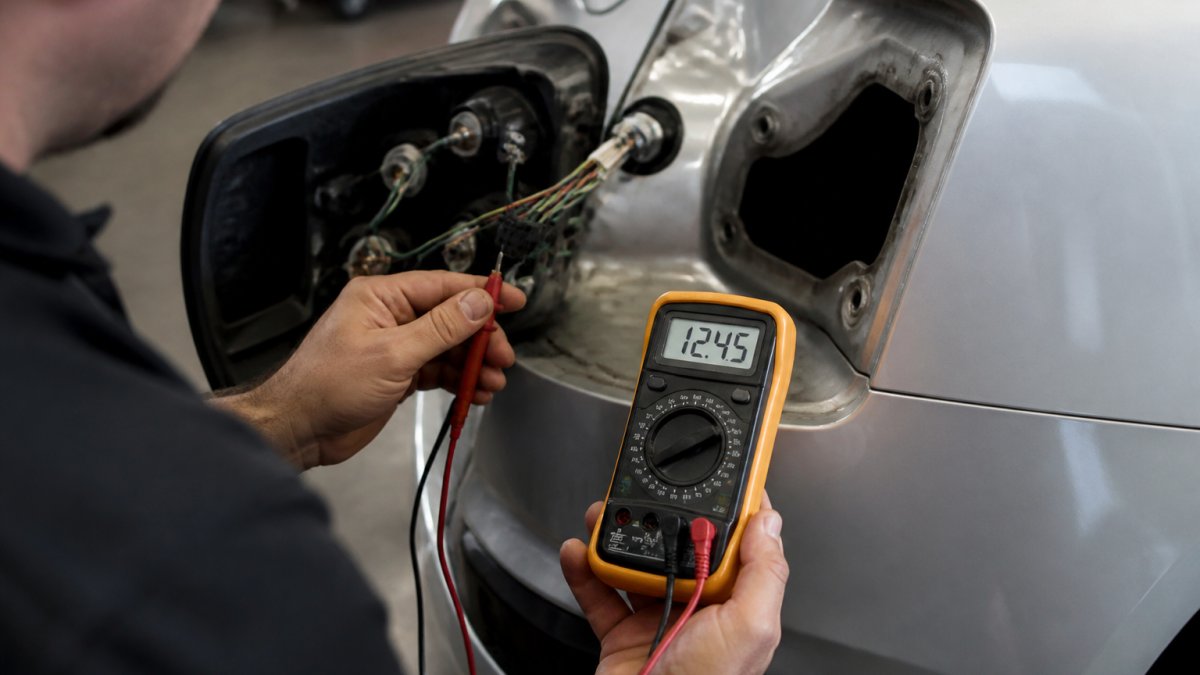
Here's how to test ground:
- Set your multimeter to resistance mode (ohms)
- Disconnect the negative battery terminal (safety first)
- Place one probe on the bulb socket's ground contact
- Place the other probe on a clean metal part of the vehicle frame
- A good ground reads 0-2 ohms. Anything higher indicates corrosion or a broken connection
To test voltage:
- Reconnect the battery
- Set your multimeter to DC voltage
- Turn on the turn signal
- Place the positive probe on the power wire, the negative probe on ground
- You should read 12-14 volts. If you read less than 10 volts, there's resistance in the circuit
If ground resistance is high or voltage low, clean or replace the ground: disconnect the wire, scrape off corrosion with a wire brush, reconnect with a fresh bolt, and apply dielectric grease to prevent future corrosion.
Inspecting Bulb Sockets, Wiring Harness, and Electrical Connections
Visual inspection catches problems multimeters miss. Spend five minutes on the hardware first.
Checking for Corrosion and Socket Damage
Remove the LED bulb and inspect the socket. Look for:
- Green or white oxidation on the contacts (corrosion)
- Pitting or dark spots on the metal contacts (age and oxidation)
- Cracks in the plastic socket (physical damage)
Corrosion is the most common culprit. Even light corrosion increases resistance and can block current flow. Clean corroded sockets with a small brass brush or fine-grit sandpaper. Wipe away debris with a dry cloth.
For severely corroded sockets, replacement is often cheaper and faster than cleaning. Socket assemblies are inexpensive and bolt in place.
Examining Wiring for Frayed Insulation and Short Circuits
Follow the wiring harness from the bulb socket back toward the firewall. Look for:
- Frayed or cracked insulation (exposed copper wire)
- Pinched or crushed wire (from door hinges or trim clips)
- Burn marks or melted plastic (sign of a short circuit)
Even a tiny crack in insulation can cause a short. Current escapes to ground instead of flowing through the bulb. The turn signal stops working, or the flasher relay behaves erratically.
If you find frayed insulation, cut out the damaged section and splice in new wire using a butt connector and heat-shrink tubing. Make sure the new wire is the same gauge as the original (typically 16 or 18 gauge for turn signals).
Testing LED Turn Signal Circuits: Multimeter Basics
A multimeter is essential for diagnosing electrical problems, and three basic measurements solve most turn signal issues: voltage, resistance, and continuity.
Measuring Voltage and Current in the Signal Circuit
Voltage tells you whether power is reaching the circuit. Current tells you whether current is actually flowing.
To measure voltage:
- Set the multimeter to DC voltage (usually marked with a V and a straight line)
- Turn on the turn signal
- Touch the red probe to the positive wire, the black probe to ground
- A working circuit reads 12-14 volts
To measure current (this requires breaking the circuit):
- Set the multimeter to DC current (marked with A)
- Turn off the turn signal
- Disconnect one end of the wire you want to test
- Insert the multimeter in the gap (red probe to the power source, black probe to the load)
- Turn on the turn signal
- The multimeter shows how much current is flowing
A typical turn signal bulb draws 0.5-2 amps depending on the bulb type. LED bulbs draw 0.1-0.3 amps. If you measure zero amps, current isn't flowing, and you have a break somewhere in the circuit.
Reading Your Vehicle Wiring Diagram
Your vehicle's wiring diagram maps every electrical circuit, where wires go, what colors they are, and how they connect. Without one, you're guessing.
Most vehicle wiring diagrams are available online through:
- Your vehicle manufacturer's website
- Haynes or Chilton repair manuals (available at auto parts stores)
- Online forums dedicated to your vehicle model
When you look at a wiring diagram, focus on the turn signal circuit.
The diagram also shows you wire colors and connector types. This prevents you from splicing the wrong wires together.
When to Replace, Repair, or Seek Professional Help
Not every turn signal problem is a DIY fix. Know your limits.
Replace the component if:
- The bulb socket is cracked or severely corroded
- The flasher relay is burned out or damaged
- The wiring is frayed beyond a simple splice repair
Repair it yourself if:
- The problem is a corroded socket (clean it)
- The flasher relay needs upgrading (swap it out)
- A wire is loose (tighten the connector)
Seek professional help if:
- You're uncomfortable working with electrical systems
- The problem involves the main wiring harness (requires experience)
- You've spent more than an hour troubleshooting without finding the issue
A professional mechanic has diagnostic tools you don't, can pull wiring diagrams specific to your vehicle's year and trim, and can identify problems in minutes that might take you hours.
At RMS Lighting LLC, we recommend upgrading to an LED-compatible flasher relay as your first step.
Frequently Asked Questions
Why are my LED turn signal bulbs not flashing at the normal rate?
LED bulbs draw far less electrical current than factory incandescent bulbs. Your vehicle's factory flasher relay detects this lower load and interprets it as a burned-out bulb, causing rapid flashing or hyperflash. An LED-compatible flasher relay or load resistor restores normal flash speed. Test your turn signal relay first to confirm it is the source of the problem before installing additional components.
How do I know if I have a bad ground on my LED turn signal?
Bad ground symptoms include dim or flickering LED turn signals, inconsistent flashing, or one-sided signal failure. Use a multimeter to test continuity between the ground wire and a clean metal part of your vehicle chassis. If you read high resistance or infinite resistance, the ground connection is faulty. Clean corroded connections, repair frayed insulation, and ensure all wiring is securely fastened to restore proper ground.
What is the difference between an LED flasher relay and a load resistor?
An LED flasher relay replaces your factory turn signal relay and is designed to work with the lower electrical load of LED bulbs, eliminating hyperflash without additional wiring. A load resistor adds resistance to the circuit to mimic the electrical load of an incandescent bulb, tricking the factory relay into normal operation. Flasher relays are simpler to install; resistors require wiring knowledge but work with any compatible relay.
Can I install an LED turn signal resistor myself if I'm not experienced with wiring?
Yes, if you follow safety steps carefully. Disconnect the negative battery terminal first. Locate the turn signal wiring using your vehicle diagram, identify correct polarity, and install the resistor in parallel with the LED bulb using waterproof connectors. Test with the ignition on before reassembling. If you are uncomfortable working with electrical systems, have a professional technician perform the installation to avoid short circuits or polarity errors.
LED turn signal issues frustrate DIY builders and everyday drivers alike. The good news is most problems follow a predictable pattern. Start with your flasher relay. If that's not the issue, test your ground and wiring. With a multimeter and basic tools, you can diagnose and fix nearly every LED turn signal wiring problem yourself. When you're ready to upgrade, the RMS Lighting LLC team has LED-compatible flasher relays and expert guidance to help you get it right the first time.