


Preventing Dashboard Error Codes With LEDs

Table of Contents
- Why LED Bulbs Trigger Dashboard Warning Lights
- What Is a CANbus Decoder and How It Prevents Error Codes
- How to Fix Hyperflashing Turn Signals With a New Relay
- Installing LED Load Resistors: Step-by-Step Guide
- LED Flicker vs. Solid Error Code: What Each One Means
- Using an OBD-II Scanner to Clear Persistent Fault Codes
- Choose the Right LED Kit the First Time
- Frequently Asked Questions
Last Updated: September 6, 2026
You replace a halogen bulb with an LED and suddenly your dashboard illuminates like a Christmas tree. The check engine light isn't on, but a bulb-out warning or a hyper-flashing turn signal tells you something is wrong. Preventing dashboard error codes with LEDs comes down to understanding why the vehicle's electrical system reacts this way and choosing the right components to manage that reaction.

These errors are predictable, diagnosable, and entirely preventable with the right knowledge and parts.
Why LED Bulbs Trigger Dashboard Warning Lights
A dashboard warning light appears because the vehicle's computer detects an electrical load that falls outside its expected parameters. Factory halogen bulbs draw a specific amount of current, and the system monitors that draw to confirm a bulb is working. An LED bulb uses far less power, which the system misinterprets as a burned-out bulb.
Your car's wiring harness and bulb-out sensor are calibrated for the resistance of a halogen filament. LEDs have a different resistance profile, and the resulting current draw is simply too low for the system to register as functional.
Some cars show a "bulb out" indicator on the dashboard cluster, while others pulse the remaining bulbs faster to draw attention.
What Is a CANbus Decoder and How It Prevents Error Codes
A CANbus decoder, sometimes called an anti-error module, is a small electronic component that simulates the electrical load of a standard halogen bulb. It sits between the vehicle's wiring harness and the LED bulb, drawing enough current to trick the body control module into thinking a traditional bulb is still installed.
Modern vehicles use the Controller Area Network (CANbus) to communicate between modules. When you install an LED, the system detects the lower current draw and logs a fault. The decoder adds the necessary electrical resistance to bring the circuit back within the acceptable range.
Not every vehicle needs a decoder. Many newer cars use pulse width modulation to control lighting, which can cause LEDs to flicker even when the load is correct. If you're driving an older vehicle without advanced bulb monitoring, you may only need a load resistor for the turn signals. For drivers with CANbus-equipped cars, however, a decoder is often the simplest path to preventing dashboard error codes with LEDs.
How to Fix Hyperflashing Turn Signals With a New Relay
Hyperflashing is the rapid blinking of a turn signal, usually twice the normal speed, and it happens when the flasher relay detects insufficient load. The relay expects a certain current draw from the bulbs; when you install LEDs, the draw drops, and the relay assumes a bulb is burned out and speeds up to warn you.

The fix is straightforward: replace the factory flasher relay with an LED-specific unit. An electronic LED flasher relay is designed to work with the lower current draw of LEDs and will restore your turn signals to a normal blink rate without adding resistors.
For example, RMS Lighting LLC offers a 2-Pin Speed Adjustable LED Flasher Turn Signal Relay that directly replaces the OEM two-pin flasher. It allows you to adjust the flashing speed from 50 to 200 cycles per minute using a small screwdriver.
| Problem | Cause | Fix | Result |
|---|---|---|---|
| Hyperflashing turn signals | Relay detects low LED current draw | Install LED-specific flasher relay | Normal blink rate restored |
| Bulb out warning on dash | CANbus detects low power consumption | Add CANbus decoder or load resistor | Warning light cleared |
| LED flicker while driving | Pulse width modulation signal | Use decoder with built-in capacitor | Steady, stable light output |
Before purchasing a relay, confirm the pin configuration. Most vehicles use a 2-pin or 3-pin flasher, and the socket style must match your vehicle's wiring harness.
Installing LED Load Resistors: Step-by-Step Guide
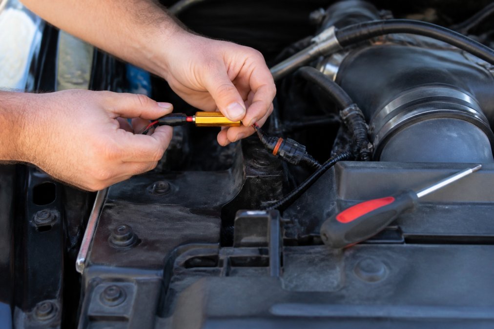
Load resistors are the universal solution for vehicles where a relay replacement isn't possible, such as cars with the flasher integrated into the body control module. A load resistor connects across the turn signal wires and draws additional current to simulate a halogen bulb.
Understanding Resistor Ratings and Heat Dissipation
A standard 1156 or 1157 turn signal bulb draws approximately 2.1 amps at 12.8 volts, which translates to roughly 27 watts of power. An equivalent LED bulb might draw only 0.2 to 0.5 amps. The load resistor must make up the difference so the vehicle's body control module (BCM) sees a current draw within its acceptable window, typically between 80% and 120% of the factory bulb's draw.
Most LED load resistors are rated at 6 ohms and 50 watts. The 6-ohm value is calculated using Ohm's law: R = V/I, where V is the system voltage (approximately 12.8 volts with the engine running) and I is the target current draw. To simulate a 2.1-amp draw, you need R = 12.8 / 2.1 ≈ 6 ohms. The 50-watt rating ensures the resistor can handle the heat generated without failing. At 6 ohms and 12.8 volts, the resistor dissipates about 27 watts of heat continuously while the turn signal is active. That heat is why mounting location is critical.
Step-by-Step Installation with Wiring Specifics
Follow these steps to install a load resistor correctly. The process is identical for most vehicles, but always verify wire colors against your vehicle's factory service manual before cutting.
-
Locate the turn signal wiring. Access the back of the bulb socket by removing the tail light or headlight assembly. On many domestic trucks and SUVs, the socket twists counterclockwise to release. On European vehicles, you may need to release a spring clip or remove a trim panel first.
-
Identify the positive and ground wires. Use a multimeter set to DC voltage to confirm which wire carries 12 volts when the turn signal is activated. Touch the black probe to a known ground (bare metal chassis) and the red probe to each wire. The wire that shows battery voltage when the signal is on is the positive feed. The ground wire will show continuity to the chassis when the circuit is off. Never rely on wire color alone, as manufacturers vary even within the same model year.
-
Splice the resistor into the circuit. Connect one resistor lead to the positive wire and the other to the ground wire. Use solder and heat-shrink tubing for a permanent connection, or use high-quality crimp connectors rated for automotive use. Do not use twist-on wire nuts, which vibrate loose and create intermittent connections that can trigger false error codes.
-
Secure the resistor to a metal heat sink. The resistor's metal case must contact bare metal to dissipate heat. Scrape away any paint or undercoating at the mounting point. Use the included stainless steel bracket and screw, or a high-temperature zip tie rated for at least 200°F. Position the resistor so it does not touch any wiring harness, plastic connector, or rubber grommet.
-
Test the lights before reassembly. Turn on the hazards and each turn signal individually. The blink rate should return to a normal 60-120 cycles per minute. If the bulb-out warning remains on the dashboard, the resistor may be wired to the wrong circuit, or the vehicle requires a different resistance value.
Where to Mount Resistors Safely
The resistor must be mounted on a metal surface that can act as a heat sink. The vehicle's chassis or a metal bracket near the tail light assembly works well. Keep the resistor away from the wiring harness and any plastic components, as surface temperatures can climb well above safe levels for those materials.
Use the included thermal adhesive tape or a zip tie to secure the resistor firmly. A loose resistor will vibrate against the body, potentially wearing through its own insulation and causing a short circuit. When installed properly, load resistors are a reliable method for preventing dashboard error codes with LEDs on virtually any vehicle.
Why One Resistor Per Side Is Not Always Enough
A common mistake is installing a single resistor for both turn signals on one side of the vehicle. Some vehicles monitor each bulb circuit independently, meaning you need one resistor per bulb socket. On vehicles with separate brake and turn signal bulbs, such as many trucks with tow packages, you may need resistors on both the brake light circuit and the turn signal circuit. Check your vehicle's wiring diagram to confirm how many circuits the BCM monitors. A single resistor on the wrong circuit will leave the error code active.
Troubleshooting a Resistor Installation That Still Shows an Error
If the dashboard warning persists after a correct installation, work through these checks in order:
- Verify the resistor value. A 6-ohm resistor is correct for most 12-volt systems, but some European vehicles require 4.7-ohm or 10-ohm units. Measure the resistor with a multimeter before installation to confirm its actual value.
- Check the ground connection. A poor ground is the most common cause of a persistent error. The resistor must have a solid path to the chassis, not just to the bulb socket's ground wire.
- Confirm the splice is solid. A cold solder joint or a loose crimp connector can create intermittent resistance that confuses the BCM.
- Test with the bulb removed. If the error clears when the LED bulb is removed but returns when it is installed, the LED itself may have an internal driver issue. Try a different LED bulb from a reputable manufacturer.
For vehicles with advanced CANbus monitoring, a load resistor alone may not be sufficient. In those cases, a CANbus decoder with a built-in capacitor provides both the resistive load and the signal smoothing needed to prevent error codes. The decoder approach is covered in the next section.
LED Flicker vs. Solid Error Code: What Each One Means
A flickering LED and a solid dashboard error code point to different underlying problems, and treating them the same way leads to wasted time and parts.
Flickering typically indicates a pulse width modulation issue. Many vehicles use PWM to dim interior lights or control the brightness of exterior lights, and the rapid on-off cycling confuses LED drivers. A CANbus decoder with a built-in capacitor smooths out the power delivery and stops the flicker.
A solid error code means the vehicle's computer has logged a fault, usually a bulb-out warning or a check engine light. This is a load detection issue, not a signal modulation issue. The fix requires adding electrical resistance through a load resistor or decoder, or replacing the flasher relay.
| Symptom | Likely Cause | Recommended Fix |
|---|---|---|
| Rapid flicker at low brightness | Pulse width modulation conflict | CANbus decoder with capacitor |
| Steady flicker at full brightness | Failing LED driver or poor ground | Check ground connection, replace bulb |
| Solid bulb-out warning | Insufficient current draw detected | Load resistor or CANbus decoder |
| Hyperflashing turn signal | Flasher relay load mismatch | LED-specific flasher relay |
Using an OBD-II Scanner to Clear Persistent Fault Codes
When a dashboard error code persists after you've installed the correct resistors or decoders, the fault may be stored in the vehicle's memory. An OBD-II scanner can read and clear these diagnostic trouble codes, but only after the underlying electrical issue is resolved.
Connect the scanner to the diagnostic port under the dashboard, typically located near the steering column. Turn the ignition to the "on" position without starting the engine, and allow the scanner to communicate with the vehicle's computer. Navigate to the "Read Codes" function to identify any stored faults related to the lighting circuit.
If the code indicates a bulb circuit fault and you've already added the correct load, clear the code and test the lights. The error should not return if the fix was applied correctly. If the code reappears immediately, the resistor or decoder may be wired to the wrong circuit, or the component itself may be faulty.
For persistent issues, consult the diagnostic trouble code reference from the EPA to understand the standardized fault categories, and cross-reference with your vehicle's service manual for model-specific details.
Choose the Right LED Kit the First Time
The most effective way to prevent dashboard error codes is to select an LED kit engineered to avoid them from the start. Cheap bulbs without built-in decoders or proper heat management will almost always trigger warnings on modern vehicles. But the deeper issue is that vehicle manufacturers take fundamentally different approaches to bulb-out detection, and understanding those differences is the difference between a plug-and-play upgrade and a weekend of frustration.
How Vehicle Manufacturers Differ in Bulb Monitoring
Vehicle electronics standards vary significantly by manufacturer, and this directly affects which LED bulbs will work without error codes.
German vehicles (BMW, Mercedes-Benz, Audi, Volkswagen) use some of the most sensitive bulb-out detection systems in the industry. Their BCMs monitor not just current draw but also the resistance profile over time. A standard LED bulb with a simple resistor may still trigger a warning because the system detects the abrupt change in resistance when the LED switches on versus the gradual change of a halogen filament. These vehicles typically require CANbus decoders with built-in capacitors that simulate the full electrical signature of a halogen bulb, not just a static resistance load.
Japanese vehicles (Toyota, Honda, Nissan, Subaru) generally use simpler current-based monitoring. A load resistor is usually sufficient to prevent error codes, and many plug-and-play LED kits work without any additional components. However, some newer models from these manufacturers are beginning to adopt more sophisticated monitoring.
Domestic vehicles (Ford, Chevrolet, Ram) fall somewhere in between. Older models with traditional flasher relays only need an LED-specific relay to fix hyperflashing. Newer models with BCM-integrated flashers may need load resistors. Ford's trucks and SUVs are generally tolerant of LED upgrades, while some Chevrolet models with the "lights on" warning system require additional resistors on the daytime running light circuit.
Vehicle-Specific Compatibility Considerations
Before ordering any LED kit, check these specific compatibility points:
- Bulb socket type. Confirm the exact bulb number (e.g., 1157, 7443, 3157) from your owner's manual. A bulb that fits physically may not have the correct pin configuration for your vehicle's socket.
- Polarity sensitivity. Some LED bulbs are polarity-sensitive and will not light if installed backward. If your vehicle uses a socket where the positive and ground wires can be reversed, look for LEDs with built-in polarity protection.
- Dual-filament applications. Brake light and turn signal bulbs that share a single socket (common on many trucks) require a dual-function LED that can handle both brightness levels. A single-function LED will either stay dim or stay bright, potentially triggering a fault.
- Pulse width modulation compatibility. If your vehicle uses PWM for dimming (common for interior lights and some exterior lights on European models), you need an LED with a driver circuit that can handle the rapid on-off cycling. Standard LEDs will flicker visibly.
What to Look for in a Kit
Look for kits that explicitly state CANbus compatibility or include anti-error modules in the package. For turn signals, verify whether the kit requires a new flasher relay or includes load resistors. Kits designed as direct replacements for factory bulbs should specify the correct socket type and bulb number.
RMS Lighting LLC tests its products rigorously to ensure they meet these standards. For example, the 1157 150W CanBus LED Chip is a dual-filament bulb with built-in CANbus compatibility, producing 40,000 lumens while maintaining the correct electrical load for brake light and turn signal circuits. The 2 Pin Hyper Flash Flasher with Ground Wire handles the relay side for vehicles that need a dedicated ground connection.

A common mistake is assuming all LEDs are interchangeable. A bulb that works in a domestic truck may not function in a European sedan with different bulb monitoring. Always confirm the bulb number against your owner's manual before ordering, and verify whether your vehicle uses CANbus monitoring.
The technical details of your vehicle's electrical system, including its bulb-out detection method, are documented in the National Highway Traffic Safety Administration's vehicle database, which can help you identify the correct components before you buy. Additionally, vehicle-specific owner forums are an excellent resource for learning which LED kits other owners have successfully installed without error codes on your exact make and model year.
Frequently Asked Questions
Why do LED bulbs cause dashboard warning lights?
LED bulbs draw far less power than the halogen bulbs your vehicle was designed for. The car's computer monitors current draw to detect bulb failures. When an LED pulls only 2-3 watts instead of the expected 21 watts, the system reads that difference as a burned-out bulb and illuminates the warning light. This is a function of electrical resistance, not a defect in the LED. A CANbus decoder or load resistor adds the missing electrical load so the computer sees normal power consumption and keeps the dashboard dark.
What is a CANbus decoder and do I need one?
A CANbus decoder is a small electronic module that simulates the electrical load of a traditional halogen bulb. It connects between your vehicle's wiring and the LED bulb, tricking the computer into thinking the original bulb is still installed. Vehicles with bulb-out indicators need decoders to prevent dashboard error codes. Some LED bulbs come with built-in CANbus circuitry. If yours do not, adding an external decoder is the cleanest solution because it generates less heat than a standard load resistor.
How do load resistors prevent hyperflashing and error codes?
Load resistors add electrical resistance to the circuit, replicating the power draw of a halogen bulb. When you install LED turn signals without resistors, the flasher relay detects lower current and blinks faster, a condition called hyperflashing. Adding a resistor restores normal current flow, which stops hyperflashing and prevents the bulb-out warning. Each resistor must be wired in parallel with the LED bulb and mounted on a metal surface because it generates heat during operation. This is a reliable fix for vehicles without CANbus systems.
Is it safe to drive with an LED-induced dashboard warning light?
Driving with a warning light caused by LED conversion is usually safe, but you should confirm the light is only a bulb-out indicator and not a separate issue. Use an OBD-II scanner to read the diagnostic trouble code and verify the fault relates to a lighting circuit. If the code points to your brake lights or turn signals, the LED bulbs themselves still function correctly. However, a warning light can hide real failures, so address the electrical load issue promptly with a decoder or relay to restore full system monitoring.