


Preventing LED Headlight Error Codes: A Complete Guide

Table of Contents
- What Causes LED Headlight Error Codes
- Understanding Your Vehicle's CANbus System
- LED Load Resistor Wiring: Installation and Setup
- CANbus Decoder Installation: A Complete Walkthrough
- Troubleshooting Flickering Headlights and Error Messages
- Selecting the Right LED Headlight Kit for Your Vehicle
- Common Installation Mistakes to Avoid
- Conclusion
Last Updated: August 11, 2026
What Causes LED Headlight Error Codes
When you install LED headlights on an older vehicle, the dashboard lights up with error messages because modern vehicles use sophisticated electrical systems that don't recognize LED bulbs the way they recognize traditional halogen bulbs. The root cause traces back to one of three issues: your vehicle's CANbus system doesn't understand the new bulbs, the electrical resistance doesn't match factory specifications, or the current draw is too low for the vehicle to register the bulbs as functional.
CANbus System Incompatibility
Your vehicle's CANbus system is a communication network that monitors every electrical component. When you install standard LED bulbs without proper adapters, the system detects that the bulbs draw far less power than the original halogen bulbs and interprets this as a bulb failure, triggering an error code. Anything built after the mid-2000s likely has this network in place. The system expects a certain voltage drop and current draw from your headlights. LEDs, being more efficient, don't meet these expectations, creating a mismatch that triggers the error.
Voltage Drop and Electrical Resistance
Halogen bulbs generate heat and consume significant power, creating a specific voltage drop across the circuit of typically around 13.5 volts at the bulb. When you swap in LEDs that only draw a fraction of that power, the voltage remains higher than expected, and your vehicle's diagnostic system flags this anomaly. Traditional bulbs have filament resistance that the vehicle's electronics recognize as normal operation. LEDs have minimal resistance, which changes how the circuit behaves. Without a load resistor or decoder to simulate the proper resistance, your vehicle's computer sees the circuit as broken.
Bulb-Out Warnings and Current Draw Mismatch
Modern vehicles monitor the current draw of each headlight circuit. When current drops below a threshold, the system assumes the bulb has burned out. LED bulbs draw so little current that they fall well below this threshold, triggering a bulb-out warning on your dashboard.
Understanding Your Vehicle's CANbus System
Your vehicle's CANbus (Controller Area Network) is essentially a digital nervous system connecting dozens of modules, the engine control unit, transmission computer, lighting controller, and others, allowing them to communicate and coordinate. When you install aftermarket LED headlights, you're introducing a component that doesn't speak this language fluently.
The CANbus system continuously monitors voltage, current, and resistance across circuits. It has baseline expectations for each component. When a headlight draws significantly less than the expected 55 watts per halogen bulb, the system recognizes the difference instantly and logs a diagnostic trouble code if it falls outside acceptable parameters. A 2008 vehicle might have basic monitoring, while a 2018 model could have advanced adaptive lighting systems that detect LED bulbs and reject them outright. Understanding how your CANbus system works means you can anticipate problems before installation and choose LED kits specifically designed to work with your vehicle's electrical architecture.
LED Load Resistor Wiring: Installation and Setup
Load resistors are the simplest solution for preventing LED headlight error codes. They work by creating electrical resistance that mimics the power draw of your original halogen bulbs, convincing your vehicle's diagnostic system that everything is normal.

How Load Equalizers Work
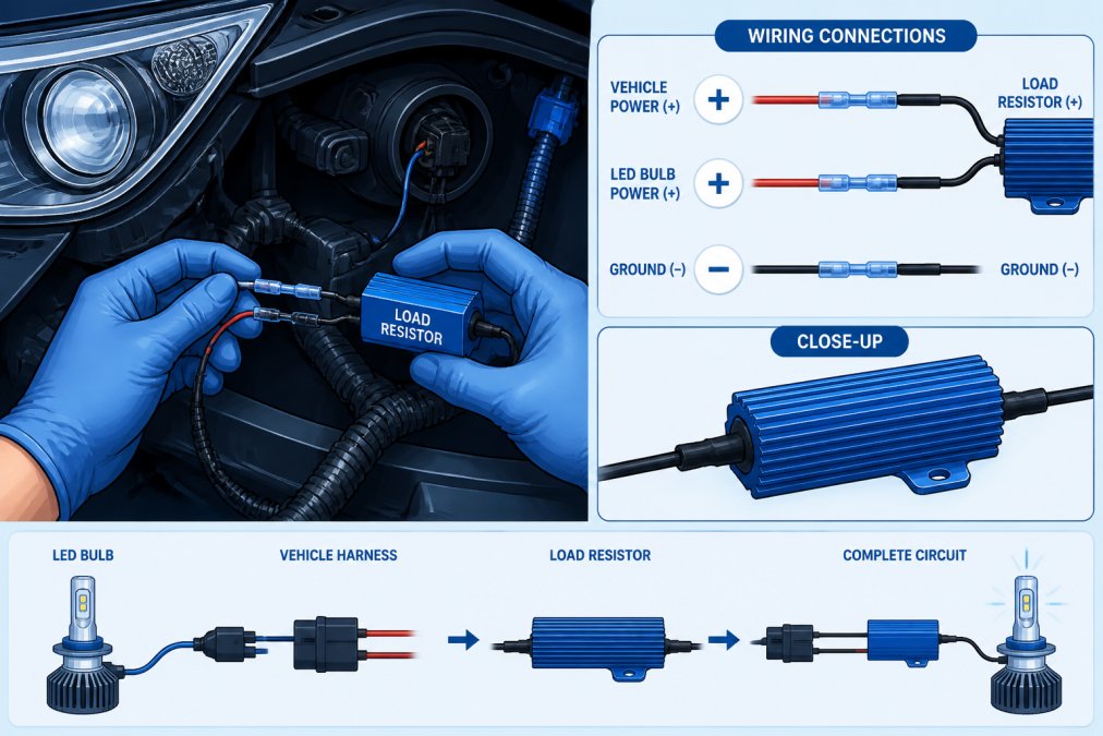
A load resistor is a small electrical component that dissipates power as heat. When wired in parallel with your LED bulb, it draws the current your vehicle expects, even though the LED itself draws very little. If a halogen bulb draws 55 watts and your LED draws 8 watts, the resistor needs to dissipate approximately 47 watts, creating the electrical signature your CANbus system recognizes as normal operation. Load resistors come in different wattage ratings, and you need to match the resistor to your specific bulb and vehicle combination.
Step-by-Step Load Resistor Installation
Installing load resistors takes about 30 minutes per headlight if you're comfortable with basic wiring:
-
Disconnect the negative battery terminal to prevent electrical shorts during installation.
-
Access the headlight assembly by removing any trim pieces or covers.
-
Locate the factory wiring harness that connects to the headlight and identify the positive and negative wires.
-
Cut the positive wire at a point where you have room to work, usually near the headlight connector or in the engine bay.
-
Strip about half an inch of insulation from each cut end of the positive wire.
-
Connect one end of the load resistor to the cut positive wire using a crimp connector or solder joint, ensuring the connection is secure and insulated.
-
Connect the other end of the resistor to the remaining section of positive wire using proper connectors and insulation.
-
Route the resistor away from heat sources like the engine or exhaust, mounting it with a zip tie or bracket to keep it stable.
-
Reconnect the battery and test your headlights. The error code should disappear within a few seconds of turning on the lights.
If the error code persists, you may have the wrong resistor rating. Take time with the wiring, poor connections are the leading cause of continued error codes.
CANbus Decoder Installation: A Complete Walkthrough
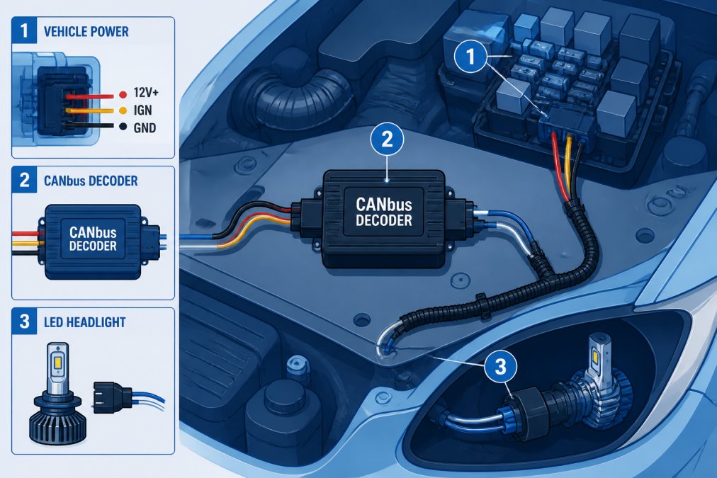
When load resistors aren't sufficient, usually because your vehicle has advanced CANbus monitoring, a decoder module becomes necessary. Decoders actively communicate with your vehicle's CANbus system, translating the LED signal into a format the vehicle recognizes.
When to Choose a Decoder Over Resistors
Load resistors work well for basic bulb-out warning elimination. Decoders are necessary when your vehicle has advanced diagnostic features such as automatic headlight leveling, adaptive front lighting that adjusts beam direction, flickering detection circuits, or advanced diagnostic systems that monitor impedance. If you install LED headlights and get an error code that persists even after adding load resistors, your vehicle likely needs a decoder.
Decoder Wiring and Connection Steps
CANbus decoders typically connect between your vehicle's OBD-II port and the headlight wiring harness. The installation process is more involved than load resistors but still manageable:
-
Locate your vehicle's OBD-II diagnostic port, usually under the steering column on the driver's side.
-
Consult the decoder's manual to identify which pins carry the CANbus signals for your specific vehicle.
-
Access the headlight wiring harness by removing trim pieces as needed.
-
Run the decoder's input wires to the appropriate OBD-II pins using a T-tap connector or carefully splicing into existing wires.
-
Connect the decoder's output wires to your LED headlight connector.
-
Ground the decoder to a solid chassis ground point. Poor grounding causes intermittent errors.
-
Secure all connections with proper connectors, solder, or crimps, wrapping exposed wires with electrical tape.
-
Test the installation by turning on the headlights and monitoring your dashboard for error codes.
-
Road test the vehicle to ensure the decoder is functioning properly.
Decoder installation requires more electrical knowledge than resistor installation. If you're not comfortable working with vehicle electrical systems, consult a professional mechanic or automotive electrician.
Troubleshooting Flickering Headlights and Error Messages
Even with proper installation, you might encounter flickering headlights or persistent error messages. These issues usually indicate a wiring problem, incompatible components, or a vehicle-specific issue that requires targeted diagnosis.
Diagnosing the Root Cause
Flickering headlights suggest an intermittent electrical connection or a component that's not properly matched to your vehicle's system. Start by checking your connections, loose crimps, corroded connectors, or improperly soldered joints cause most flickering issues. If connections are solid, the problem might be voltage drop in the wiring. Long runs of undersized wire between the battery and headlights can cause voltage to drop below what your LED bulbs need to function properly.
Error messages that won't clear despite proper installation suggest your vehicle's diagnostic system isn't recognizing the solution. This could mean the load resistor or decoder isn't rated for your specific vehicle, your vehicle has a more advanced CANbus network than anticipated, or the LED bulbs themselves are incompatible with your vehicle's headlight housing.
Testing Polarity and Impedance
Polarity errors are a common cause of persistent problems. LEDs are polarity-sensitive and only work when positive and negative are connected correctly. Check polarity by examining the LED bulb connector, most modern LED headlight bulbs have clearly marked positive and negative terminals. Trace these connections back through your wiring to ensure they match your vehicle's original wiring color codes.
Impedance testing requires a multimeter. Set it to resistance mode and measure the impedance across your headlight circuit with the lights off. Compare this reading to your vehicle's factory specifications. Significant differences indicate a problem with your load resistor, decoder, or wiring.
Selecting the Right LED Headlight Kit for Your Vehicle
Not all LED headlight kits are created equal. Compatibility varies significantly based on your vehicle's year, make, model, and existing electrical architecture. Choosing the right kit from the start prevents most LED headlight error codes from occurring.
Compatibility Between LED and Halogen Systems
Your vehicle's headlight housing was designed for halogen bulbs. The reflector shape, lens design, and heat management all assume a halogen light source. When you install LEDs, you're introducing a fundamentally different light source into a system designed for something else. This creates two compatibility issues: optical compatibility (the LED beam pattern matches what the housing was designed to produce) and electrical compatibility (the LED's power draw and electrical characteristics match what your vehicle's system expects).
The best LED kits address both issues. They're designed specifically for your vehicle's headlight housing, ensuring proper beam pattern, and include integrated CANbus compatibility through built-in decoders or resistors. RMS Lighting LLC specializes in LED headlight kits designed for specific vehicle applications. Their RMSH4S130 - 130W Canbus LED Bulb's (Pair) 6500K and similar products are engineered with CANbus compatibility built in, meaning they're designed to work with your vehicle's diagnostic system from day one.

Checking Thermal Management and Heat Dissipation
LEDs generate less heat than halogen bulbs, but they still need proper thermal management. Poor heat dissipation causes LEDs to dim over time and can shorten their lifespan. Quality LED headlight kits include heat sinks and thermal management systems that keep the LED junction temperature within safe operating ranges. Look for active cooling features, aluminum heat sinks that dissipate heat passively or small fans for active cooling. The LED junction temperature should remain below 150°C under normal operating conditions.
Common Installation Mistakes to Avoid
Most LED headlight error codes result from preventable installation mistakes. The most frequent mistake is installing LED bulbs without any load resistor or decoder. Another common error is using the wrong load resistor rating, the resistance value must match your specific LED bulb's power draw and your vehicle's expected current draw.
Poor wiring connections cause flickering and intermittent errors. Crimped connections that aren't properly seated, solder joints with cold spots, or loose wire connections all create electrical resistance that interferes with the signal. Improper grounding is another frequent culprit, all electrical circuits need a solid ground path. Always ground to bare metal on the vehicle chassis, not to painted surfaces or plastic components. Installing the wrong type of LED bulb in your specific headlight housing produces poor beam patterns and can trigger error codes.
Conclusion
Preventing LED headlight error codes comes down to understanding your vehicle's electrical system and choosing compatible components. Whether you opt for load resistors, a CANbus decoder, or a purpose-built LED kit with integrated compatibility, the key is matching the solution to your specific vehicle's requirements.
RMS Lighting LLC offers LED headlight kits specifically engineered for CANbus compatibility, eliminating guesswork from the installation process. Their products feature precision-engineered designs with correct LHD lens patterns and integrated solutions that work seamlessly with your vehicle's diagnostic systems. Get started with RMS Lighting LLC and experience the improved visibility and reliability that comes from properly installed LED headlights designed to work with your vehicle's electronics.
| Component | Purpose | Best For |
|---|---|---|
| Load Resistor | Mimics halogen power draw | Simple vehicles with basic CANbus monitoring |
| CANbus Decoder | Translates LED signal to vehicle language | Advanced vehicles with sophisticated diagnostics |
| Integrated LED Kit | Built-in compatibility solution | Any vehicle, eliminates compatibility guesswork |
| Thermal Management | Keeps LEDs cool and reliable | All LED installations for longevity |
NHTSA headlight safety standards and regulations
SAE International automotive electrical standards for lighting
Automotive electrical system diagnostics and CANbus technology overview
Frequently Asked Questions
Why do LED headlights cause dashboard error codes?
LED bulbs draw significantly less current than halogen filaments. Your vehicle's CANbus electrical system monitors current draw to detect burned-out bulbs. When LEDs draw less power, the system interprets this as a bulb failure and triggers an error code. Additionally, LEDs lack the same electrical resistance as halogen bulbs, causing voltage fluctuations that confuse the vehicle's diagnostic sensors. This incompatibility between modern LED technology and older halogen-designed electrical systems is the primary cause of bulb-out warnings and dashboard error messages.
Is a load resistor or CANbus decoder better for preventing LED headlight error codes?
Both solutions work, but they address the problem differently. Load resistors simulate the electrical resistance of halogen bulbs by drawing extra current, tricking your vehicle's system into thinking the original bulbs are still installed. CANbus decoders intercept the error signal before it reaches your dashboard, preventing the warning from displaying. For most vehicles, a quality load resistor is simpler and more cost-effective. However, some newer vehicles with advanced diagnostic systems benefit more from a decoder. Your choice depends on your vehicle's year, make, model, and the specific LED kit you're installing.
Will LED load resistor wiring work on my older vehicle?
Load resistor wiring is most effective on vehicles from the 1990s through early 2010s. Older vehicles with simpler electrical systems may not require resistors at all, while newer vehicles with sophisticated CANbus networks may need decoders instead. The key is understanding your vehicle's electrical architecture. Before purchasing resistors, check your vehicle's year and consult your LED kit documentation. If your vehicle has OBDII diagnostics and monitors bulb current, resistors will likely solve your error code problem. Always verify compatibility with your specific vehicle model before installation.
What's the difference between plug-and-play LED kits and kits that require resistors or decoders?
Plug-and-play LED kits are designed with built-in CANbus compatibility, meaning they include resistors or decoders already integrated into the bulb or harness assembly. These kits simply screw into your headlight housing with minimal wiring. Standard LED bulbs without this technology require you to purchase and install separate load resistors or decoders to prevent error codes. While plug-and-play kits cost more upfront, they eliminate installation complexity and compatibility guesswork. For DIY enthusiasts without advanced wiring experience, plug-and-play options save time and reduce the risk of installation errors that trigger error codes.
This article was written using GrandRanker